Flash Vessel - FT Series
Fabricated Vessels
![]() FT Series - PRODUCT DATA BULLETIN
FT Series - PRODUCT DATA BULLETIN![]() FT Series - INSTALLATION, OPERATION AND MAINTENANCE MANUAL
FT Series - INSTALLATION, OPERATION AND MAINTENANCE MANUAL
Series 'FT' Flash Tanks
COLTON flash tanks offer a unique inlet baffle arrangement designed to enhance flash separation and extend tank life.
All steam systems produce flash steam which is usually wasted when it escapes through the condensate receiver vent pipe. The COLTON flash tank allows you to use this waste energy by capturing the flash steam and using it elsewhere in your system.
Flash steam is exactly the same as live steam and is every bit as useful. Flash steam should be regarded as a free source of low pressure steam in any system that operates with more than one steam pressure.
Ordering Information Required:
- Pressure at high pressure steam trap/s or blow down metering valve/s feeding the flash tank.
- Volume of high pressure condensate (usually expressed in lbs/hr.)
- Pressure of the lower pressure system that we will be supplementing.
- Steam trap and strainer
- Pressure gage, syphon and pet cock
- Safety valve
- Drip pan elbow
- Back pressure regulator
- Pressure reducing valve
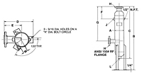
Item Number |
A |
B |
C |
D |
E |
F |
G |
H |
J |
|---|---|---|---|---|---|---|---|---|---|
| FT6-150 FT6-150/Asset/flash-tank-image.jpg | A N/A 6 in | B N/A 47 in | C N/A 38 in | D N/A 13 in | E N/A 8.00 in | F N/A 9 in | G N/A 25 1/2 in | H N/A 2.50 in | J N/A 3/4 in |
| FT8-150 FT8-150/Asset/flash-tank-image.jpg | A N/A 8 in | B N/A 48 in | C N/A 39 in | D N/A 14 1/2 in | E N/A 8 1/2 in | F N/A 9 1/2 in | G N/A 26 in | H N/A 4 in | J N/A 1 in |
| FT12-150 FT12-150/Asset/flash-tank-image.jpg | A N/A 12 in | B N/A 49 1/2 in | C N/A 42 in | D N/A 20 in | E N/A 12 in | F N/A 11 1/2 in | G N/A 27 in | H N/A 5 in | J N/A 1 1/2 in |
| FT16-150 FT16-150/Asset/flash-tank-image.jpg | A N/A 16 in | B N/A 58 in | C N/A 49 in | D N/A 23 1/2 in | E N/A 13 1/2 in | F N/A 12 1/2 in | G N/A 32.00 in | H N/A 6 in | J N/A 2 in |


